Bottom Ash Drain Valve Upgrade - UK Energy from Waste
Client:
UK Energy from Waste Plant
Challenge:
ValvePro Limited were requested to attend site at a UK Energy from Waste Plant as they were having issues operating existing Bottom Ash Drain Valve arrangements on their (4) Bottom Ash Tanks, and wished to upgrade these in their up-coming Maintenance Outage.
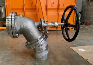
The Valve in-situ (Figure 1) had been installed at commissioning phase, and whilst it had initially provided a means to drain the Tank, the particularly tough application, coupled with a basic fabricated Valve design had caused the Valve to become stuck in the closed position (Figure 2) and thus inoperable without painstakingly chipping away the crystallised Ash and exerting excess Torque on the Handle. In doing so, plant operators had sheered the Stem from the Discs on 2 Valves and rendered them inoperable.
Clearly, this is not a solution designed to last in long-term service and left the Plant with an operational issue after their Warranty Period had expired. ValvePro were tasked with designing an upgraded Valve solution, which would not only increase the functionality and reliability of the System but also ensure that the media that was drained from the tank was diverted directly 90° below into the drains to flush to the Ash Handling facility, for further usage in the Construction industry.
In addition to the above, the client’s outage was 12 working weeks from date of site visit, in which time ValvePro had to Design, Source, Manufacture and Deliver these upgraded Bottom Ash Drain Valves.
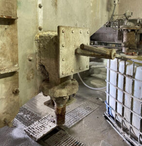
Figure 1: Existing fabricated Drain Valve
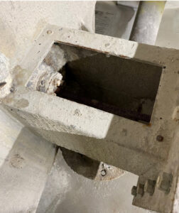
Figure 2: Existing ‘Drain Valve’ Sealing arrangement. The Valve Disc is inoperable due to crystallisation of the bottom ash media.
ValvePro Solution:
It is our mission to ensure that every Valve supplied by ValvePro is the optimum solution for the application. This measure requires taking into account all contributing factors, Operating Parameters, Location on Site, Frequency of Operation, Material Selection etc. and this occasion was no different. We believe that a quality Valve will in the long-run pay dividends when compared with a lower quality alternative such as the original product installed in this case.
Having reviewed the contributing factors above, ValvePro identified the correct Valve for the application and set about designing piping spools around this Valve Design to ensure correct diversion to the below Drain. Firstly, the valve would require a Stem and Sealing arrangement robust enough to accept the high torque required to break the crystallised sediment layer and allow the tank to drain. To achieve this, the valve would have to protrude away from the main Body and penetrate into the tanks, thus breaking the sediment layer. This is the opposite from ‘Standard’ Valves.
Additionally, as the Valves are draining process Ash, the Valve will need to divert with a smooth, uninterrupted flow path to ensure little to no build up will occur in the body itself. ValvePro identified a manufacturer that could not only supply the correct Valve Type/Design, in materials suitable for the application, but also deliver the material within the tight delivery schedule.
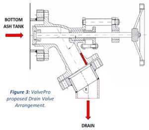
Figure 3: ValvePro proposed Drain Valve arrangement.
Figures 4a and 4b: Tank Bottom Darin Valve arrangements in the open and closed positions.
Services and products delivered:
Following a comprehensive review of Client’s application, ValvePro sourced the optimum Valve Solution, Designed Inlet and Outlet Spool Pieces to weld to the Tank Bottom but crucially with a non-standard ID Ø which would accept the Valve’s unique design, and also safely drain the Bottom Ash media into the Drains below.
ValvePro delivered the completed Assemblies in 12 working weeks from initial Site Walkdown, which included: Design, Procurement of Material, Manufacture and certification of the Assemblies. The Assemblies were delivered on-time leaving site plenty of time to plan the works and arrange permits for their Outage Timeframe.
ValvePro’s overall Scope of Supply (per assembly) is as follows:
- DN200 (8”) Tank Bottom Drain Valve.
- Inlet Spool Piece, to be welded to Bottom Ash Tank.
- Outlet Spool Piece, 30° Elbow to drain Bottom Ash to below grate.
- Fasteners and Spiral-Wound Gaskets.
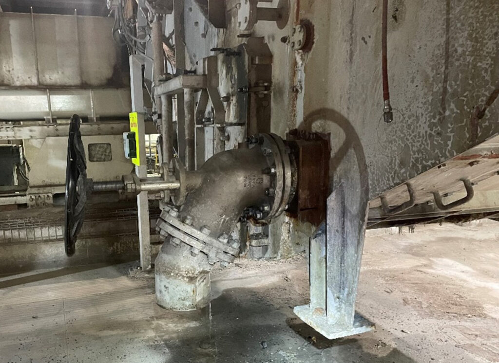
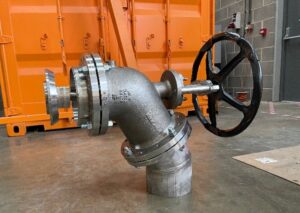
Figure 5: Tank Bottom Drain Valve arrangement installed on site.