Feedwater Control Valve – Severe Service Trim Upgrade
Client:
UK Energy from Waste Power Station
Challenge:
ValvePro were approached by the Mechanical Engineer at a UK Energy from Waste Plant with a request to assist them with an issue with their Feedwater Control Valve providing sufficient level of Control required to regulate the flow of feedwater supplied to the Boiler, one of the most critical applications on-site for safe boiler operation.
ValvePro Solution:
Following an initial site meeting with the Engineer to get a better understanding of the issues site were facing, it seemed highly probable that the internal components may have suffered from Cavitation or Flashing which are common Control Valve problems in feedwater applications, and hence were not providing the Flow Rates that were originally sized. As well as the lack of control reported, the Engineer advised there was significant noise being omitted from the Valves.
In conjunction with our partner – Carter Process Control (CPC), we carried out a detailed review of the Clients OEM Sizing Data Sheets and performed our own Sizing Calculations based on the Inlet Pressure, Outlet Pressure, Flow Rates, Vapour Pressures etc. (See Figure 1), and it was noted that the maximum Pressure Drop across the Valve was 743 psi A (52 Bar). The existing Valve had a two stage Drilled Hole Cage Design that would allow a Pressure Drop of 26 bar to be taken across each stage of the cage.
‘Flashing’ can only occur when the Valve Outlet Pressure is lower than the Vapour Pressure of the Liquid, as the Outlet Pressure was significantly higher flashing of the feedwater could not have caused the issue. However, the Valve Sizing Data indicated the potential for the onset of incipient cavitation with the existing two cage trim design. Cavitation occurs when the static pressure at the Vena Contracta is lower than the Liquid Vapour Pressure, causing formation of vapour bubbles in the liquid which then implode as the pressure recovers at the Outlet of the Valve. These implosions cause localised damage to the Valve Body and Trim components and generate excessive noise and mechanical vibration.
In addition to the potential for incipient cavitation, it is also noted that there was excessive velocities generated by the uncontrolled Pressure Drop, which were reported at 47.1 m/s. As per industry standard ISA S75.01 guidelines, it is recommended that the Trim outlet velocity should be limited to a maximum of 30 m/s. High velocities across the valve will result in excessive erosion and lead to premature valve failure, mechanical vibrations and excessive noise. This in turn leads to instability of the trim and loss of control as reported by the Engineer.
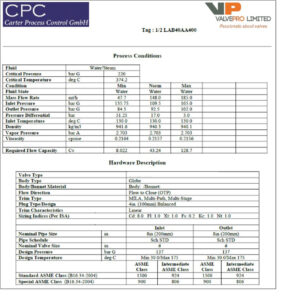
Figure 1: Process Conditions and Sizing Data.
Once we had presented the results of our findings to the client, ValvePro were then tasked with providing a solution which not only provided the required Pressure Drop, significantly reducing the Noise and Vibration, but also ensuring that the upgraded trim would also fit within the existing Valve Body so that no Pipe Modifications, Stress Analysis or Actuator Replacement was required.
To eliminate the aforementioned erosion issues associated with the application, Carter Process Control offered a Multi-Stage MILA Severe Service Trim with 6-stages of pressure reduction (see Figure 4), specifically sized to the exacting process conditions required of the clients Feedwater system. This trim design provides accurate control of both Pressure Drop and associated Fluid Velocities by “turning” the fluid through a series of tortuous flow paths.
Accurate control of the Pressure Drop across the trim ensures that at no point will the static pressure fall below the Vapour Pressure, thereby entirely eliminating the potential for incipient cavitation to occur.
By apportioning the pressure drop across an increased number of stages, the maximum trim exit velocity was reduced to 26.6 m/s, within the recommended ISA S75.01 guidelines to prevent erosion and eliminate mechanical vibration. This will also ensure that the maximum noise level across the Valve does not exceed 75dBa.
In addition, it was noted that the existing Trim Materials were manufacture from 1.4571 (316) Stainless Steel. We offered Heat Treated and Hardened 410 Stainless Steel that would provide superior resistance to degradation when compared with 316 Stainless Steel in this particular application.. As a result, the Severe Service Disk Stack, Lower Cage, Plug Assembly and Seat Ring were all manufactured from 410 Hardened Stainless Steel (see Figure’s 2, 3 & 4).
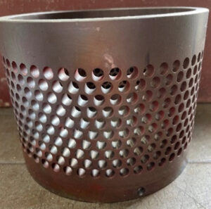
Figure 2: 316 Stainless Steel Lower Cage.
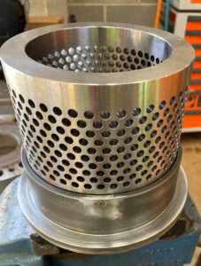
Figure 3: Upgraded Hardened Stainless Steel Lower Cage.
Conclusion:
ValvePro Scope of Supply included:
- Full strip-down and internal inspection of existing Valve.
- Complete Design Analysis and Sizing Calculations with client’s operating parameters.
- Design of Severe Service Trim, to fit into existing Valve Body and provide sufficient Pressure Drop and Outlet Velocity Control to reduce the risk of Cavitation.
- Manufacture all trim components in Hardened Stainless Steel, to upgrade the standard 316SS trim of the existing Valve.
- Assemble new trim into Valve Body and re-build the Valve.
- Hydrostatic Shell Test of the Valve Assembly, 1.5x the Maximum Working Pressure (i.e. 240 bar), testing carried out at ValvePro’s Huddersfield Facility.
- Shotblast and Paint the completed Valve Assembly and deliver to client.
The above scope of supply was carried out in a 12 week time-frame to meet clients stringent Outage Schedule. This allowed the Valve to be installed with no pipe modifications or Actuator Replacement, as the Valve face to face and Travel dimensions remained the same as the OEM Valve.
Following successful commissioning of the Valve, the Client has also planned to upgrade their second Feedwater Control Valve to a CPC Mila Severe Service Trim, and we are also discussing further potential applications where this technology can be utilised.
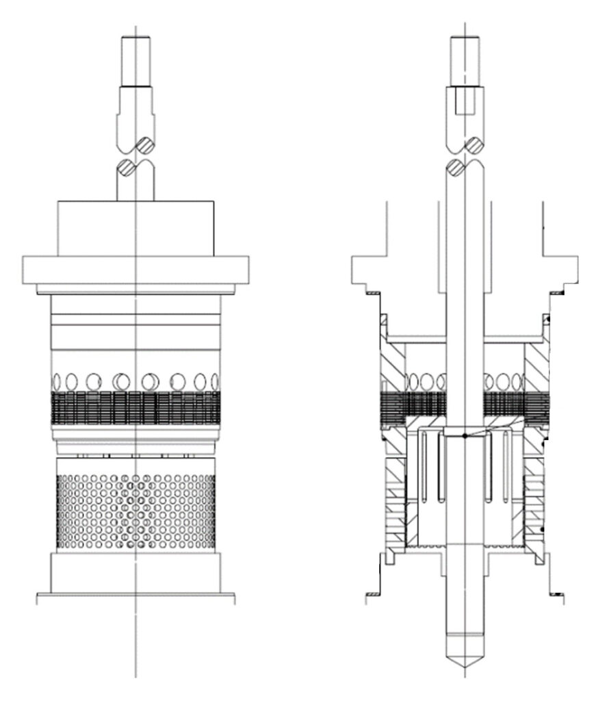
Figure 4: Internal trim assembly drawing.
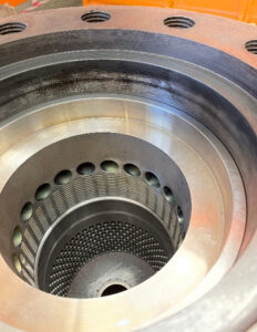
Figure 5: Severe Service Disc Stack installed in Valve.
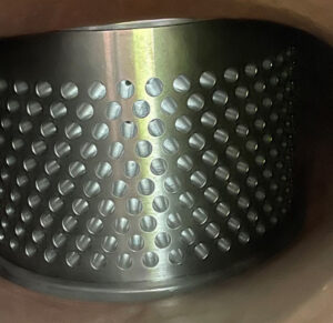
Figure 6: Lower Cage installed in Valve.
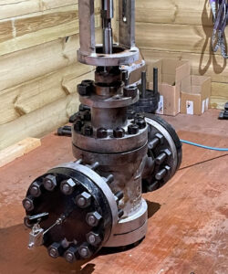
Figure 7: Valve undergoing Hydrostatic Shell Test.
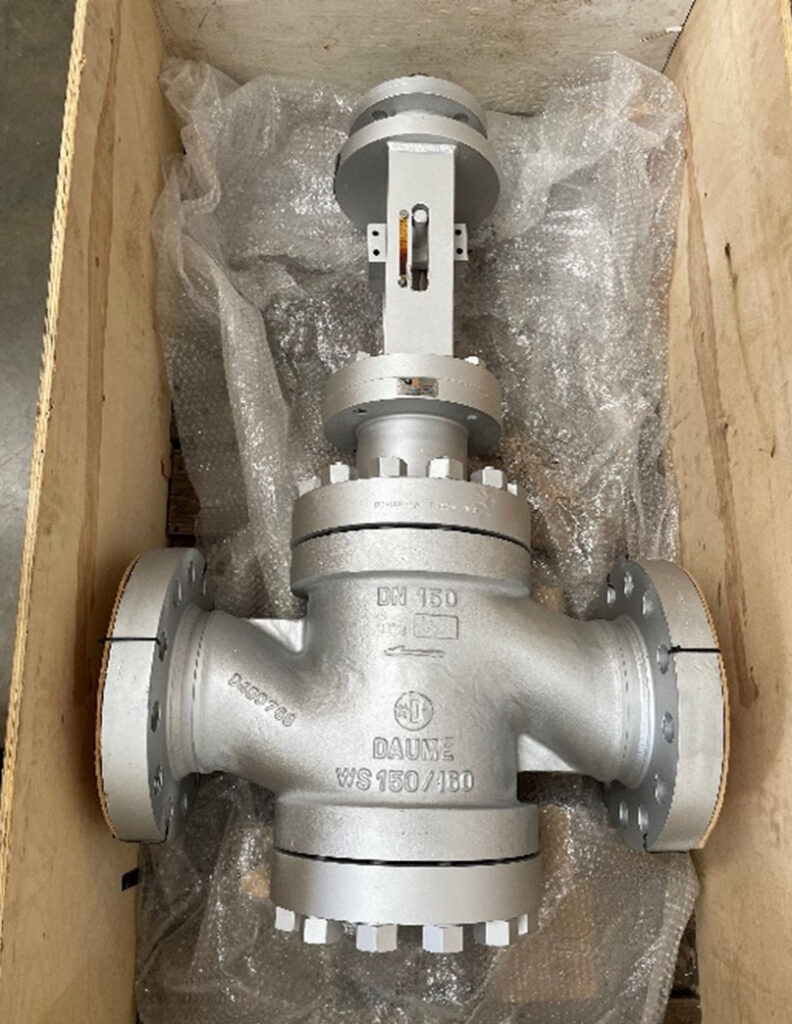
Figure 8: Valve prior to delivery to the Client after Build, Test, Shotblast and Paint.